Call: 07971670681
 Send Inquiry
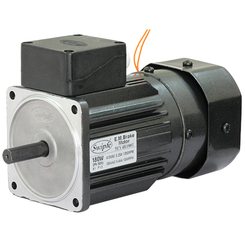
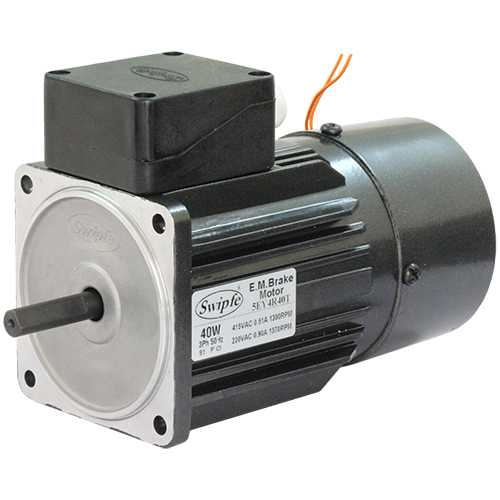
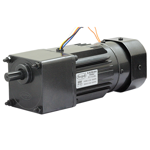
Continuous Rating with Frequent Start Stop,
Load Holding & Minimum Overrun.
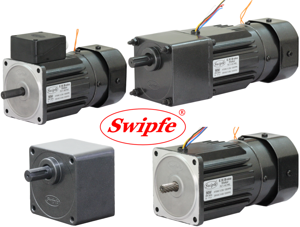
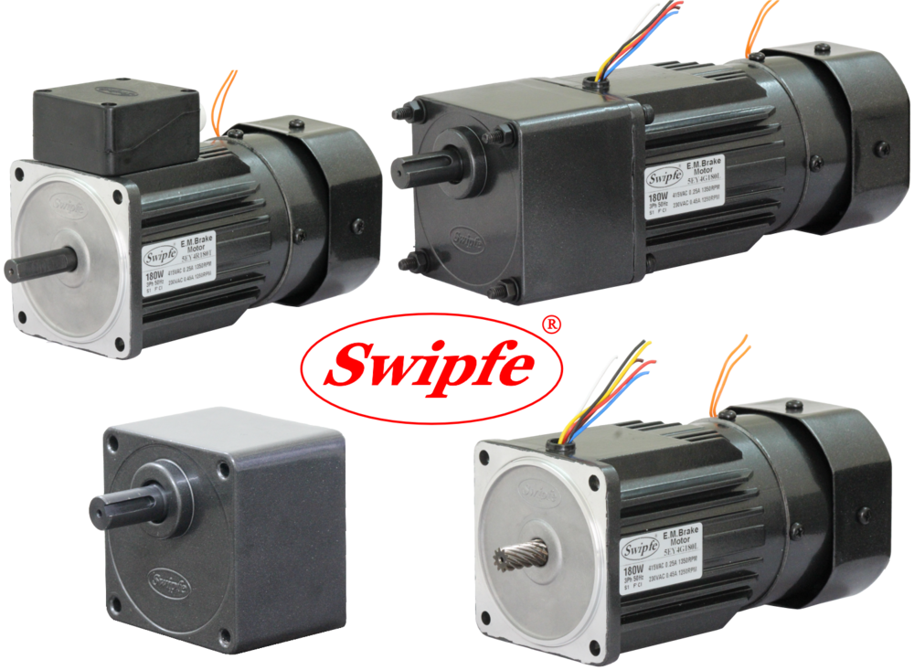
Electromagnetic Fail Safe Brake (Power Off activated)
Fitted at the Back of Induction Motor.
Rotates in Clockwise or Counter Clockwise Direction.
Terminal Box or Lead Wires for Connection.

| Model | Supply | Frequency Hz |
Stall Torque Nm |
Rated Torque Nm |
Rated Speed RPM |
Rated Current Amp |
Capacitor F |
|---|---|---|---|---|---|---|---|
| 5EX4180 | Single Phase 230V | 50 | 1.45 | 1.22 | 1350 | 1.10 | 7 |
| 5EY4180 | Three Phase 230V | 50 | 1.50 | 1.34 | 1250 | 0.90 | - |
| 5EY4180 | Three Phase 415V | 50 | 1.94 | 1.22 | 1350 | 0.48 | - |
| 5EX2180 | Single Phase 230V | 50 | 0.75 | 0.61 | 2700 | 1.10 | 4 |
| 5EY2180 | Three Phase 230V | 50 | 0.66 | 0.61 | 2600 | 0.90 | - |
| 5EY2180 | Three Phase 415V | 50 | 1.10 | 0.61 | 2700 | 0.51 | - |
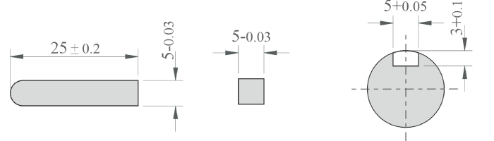
Indicates type of Shaft, G - Gear, R - Round, F - Frame, C - Custom
The maximum permissible torque is 20 Nm
No Load speed of Motor at 50Hz is approx. 1440RPM
| RPM | 480 | 400 | 288 | 240 | 192 | 160 | 115 | 96 | 80 | 57 | 48 | 40 | 29 | 24 | 19 | 16 | 14 | 12 | 9.6 | 8 |
|---|---|---|---|---|---|---|---|---|---|---|---|---|---|---|---|---|---|---|---|---|
| Gear Ratio | 3 | 3.6 | 5 | 6 | 7.5 | 9 | 12.5 | 15 | 18 | 25 | 30 | 36 | 50 | 60 | 75 | 90 | 100 | 120 | 150 | 180 |
| Output Torque | 3.4 | 4.1 | 5.7 | 6.8 | 8.5 | 10.2 | 12.8 | 15.3 | 18.4 | 20.0 | 20.0 | 20.0 | 20.0 | 20.0 | 20.0 | 20.0 | 20.0 | 20.0 | 20.0 | 20.0 |
The Gear Boxes are sold Seperately.
A coloured background indicates gear shaft rotation in same direction as motor shaft.
A white background indicates gear shaft rotation in opposite direction to the motor shaft.
The speed of geared motor is calculated by dividing motor's no load speed by the gear ratio.
The actual speed is less than the displayed value, depending upon the load.
Characteristics, specifications and dimensions are subject to change without notice.


Max. Weight:
Motor - 4.5 kg
Gear Box - 1.7 kg

When SW1 is switched ON, Electromagnetic Brake is released & motor starts rotating. When SW1 is switched OFF then electro- magnetic brake will be applied stopping the motor immediately & holding the load.
Apply voltage on the orange brake lead wires only, to release the Electromagnetic Brake.
To change the direction of rotation, flip CW to CCW.

When SW1 is switched ON, electromagnetic Brake is released & motor starts rotating. When Swl is switched OFF then electro- magnetic brake will be applied stopping motor immediately, holding the load.
Apply voltage on the orange brake lead wires only, to release the Electromagnetic Brake.
To change the direction of rotation, interchange any two wires between U, V & W.

Price:
Price 6000.0 INR / Piece
Minimum Order Quantity : 1 Piece
Protect Feature : Totally Enclosed
Frequency (MHz) : 5060 Hertz (HZ)
Usage & Applications : Industrial
Features : Durable
Price 3030.0 INR / Piece
Minimum Order Quantity : 1 Piece
Protect Feature : Totally Enclosed
Frequency (MHz) : 5060 Hertz (HZ)
Usage & Applications : Industrial
Features : Overload Protection

Minimum Order Quantity : 1 Unit
Protect Feature : Totally Enclosed
Frequency (MHz) : 5060 Hertz (HZ)
Usage & Applications : Industrial
Features : Durable
Minimum Order Quantity : 1 Unit
Protect Feature : Totally Enclosed
Frequency (MHz) : 5060 Hertz (HZ)
Usage & Applications : Industrial
Features : High quality
GST : 27AAPCS1067H1Z2

 Send Inquiry
